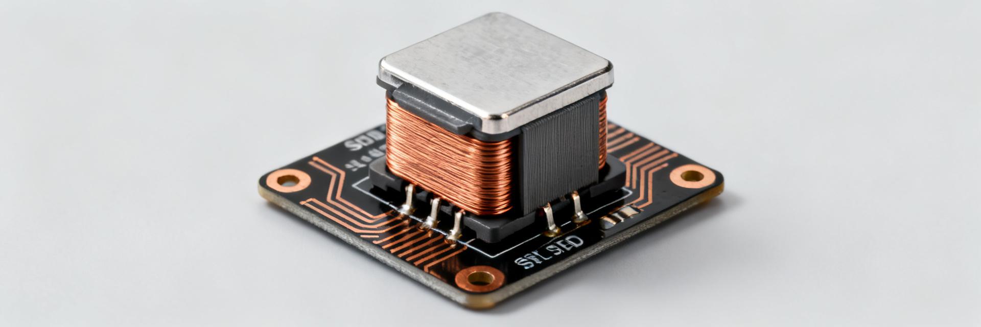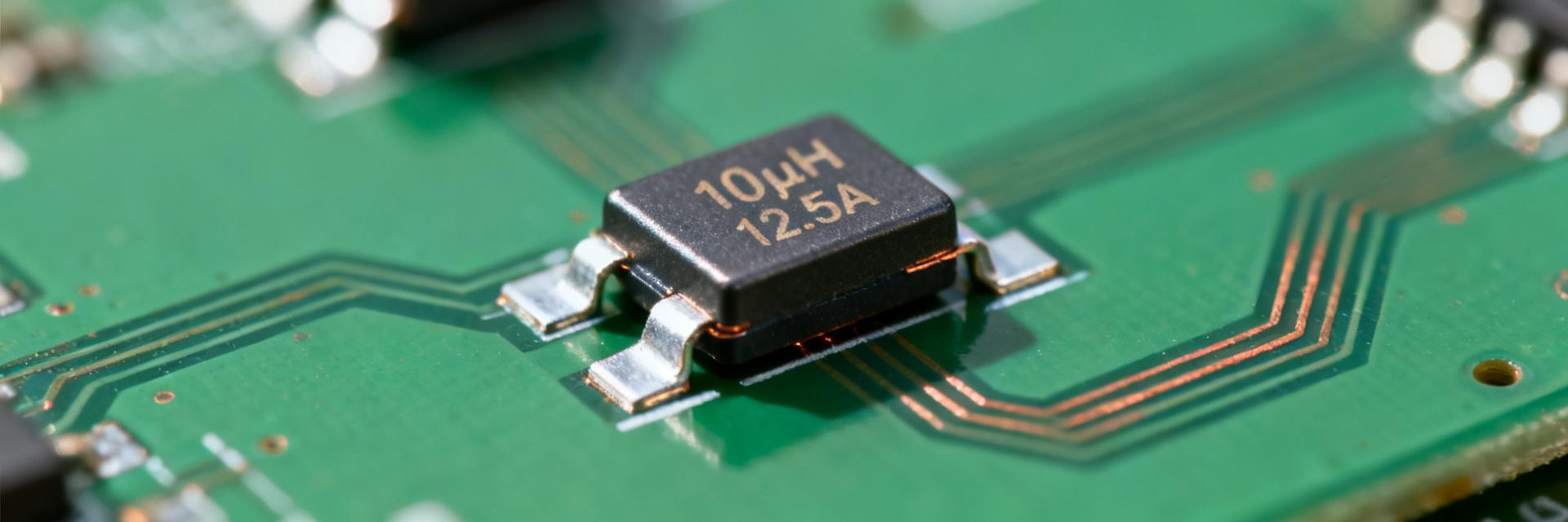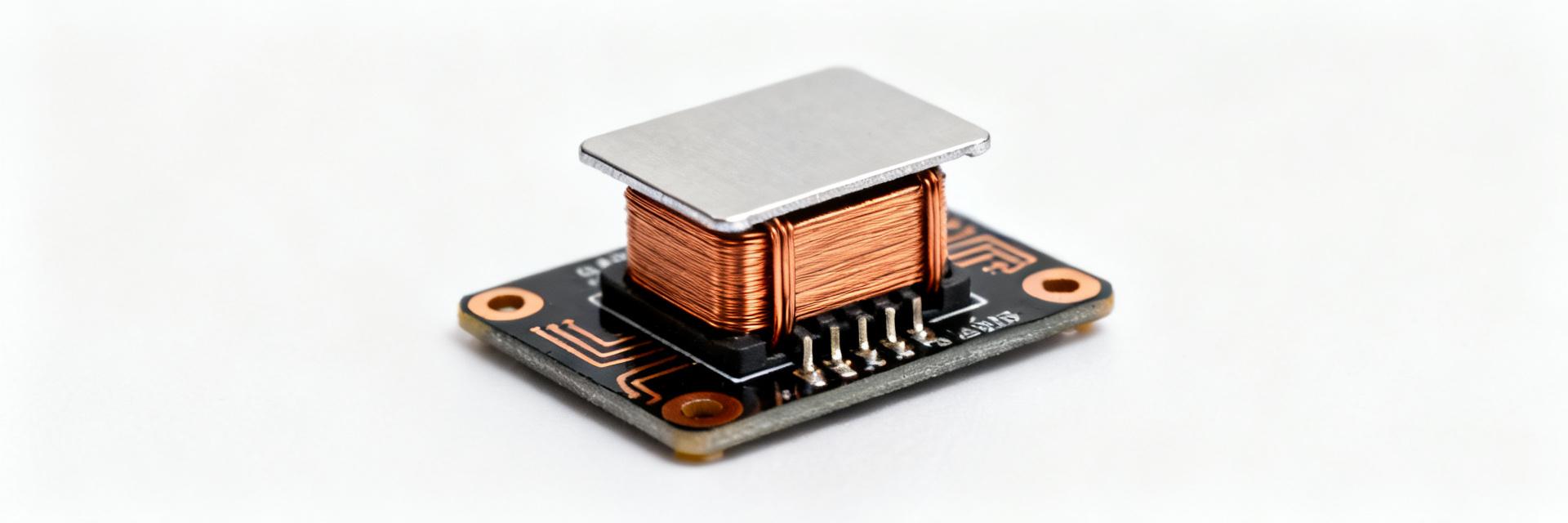
Design teams often scan a part’s top-line specs in under 60 seconds to confirm physical fit, thermal margin, and electrical current capability. This concise snapshot extracts the most critical datasheet items for the Eaton Bussmann HCM1A0703V3-8R2-R high-current power inductor, enabling engineers to rapidly decide whether to proceed to full hardware evaluation. This brief uses precise technical parameters to prioritize the critical metrics you must verify prior to starting your PCB layout or locking the BOM.
(1) Part overview & numbering breakdown — Background introduction
Part-number decoding
Point: The HCM1A0703V3-8R2-R part number directly encodes its product family, physical enclosure size, electrical value, and revision level.
Evidence: Eaton’s standard nomenclature maps specific characters to structural and electrical values.
Explanation: Read the code left-to-right: HCM1A designates the high-current power inductor family qualified for automotive application; 0703 denotes the physical package envelope (nominally 7.4 mm × 7.0 mm × 3.0 mm); V3 points to the third-generation high-performance design; 8R2 designates a nominal inductance of 8.2 µH; and the final -R denotes RoHS compliance. Consult the complete datasheet to correlate alternate reel and packaging configurations.
Typical applications and target systems
Point: This high-current shielded inductor is engineered for compact DC-to-DC converters and EMI suppression duties.
Evidence: Standard application topologies include automotive electronic control units (ECUs), point-of-load (POL) power converters, body electronics, and switch-node filter stages.
Explanation: With its high current carrying capacity and AEC-Q200 Grade 1 qualification, the component is optimized to survive the harsh temperatures of automotive passenger cabins and demanding industrial systems. Include this component during early-stage power tree mapping to guarantee EMI compliance at the system level.
HCM1A0703V3-8R2-R — Key electrical specs (data analysis)
Primary electrical parameters to highlight
Point: Extracted electrical specifications are summarized below to expedite direct comparisons during power-stage design.
Evidence: The official Eaton product specification table details nominal inductance, DC resistance, maximum continuous current, and saturation thresholds.
Explanation: Review these parameters under the specified test conditions (e.g., inductance measured at 100 kHz, 0.1 Vrms, 25°C) to prevent operating the magnetic core beyond its linear region.
| Parameter | Value (HCM1A0703V3-8R2-R) | Test Condition / Standard |
|---|---|---|
| Inductance (L) | 8.2 µH ±20% | 100 kHz, 0.1 Vrms, 0.0 Adc, 25°C |
| DC Resistance (DCR) Typical | 38.0 mΩ | 25°C nominal |
| DC Resistance (DCR) Maximum | 43.6 mΩ | 25°C maximum limit |
| Rated Current (Irms) | 4.8 A | 40°C temperature rise from 25°C ambient |
| Saturation Current (Isat) | 6.5 A | Typical 30% roll-off in nominal inductance |
| Self-Resonant Frequency (SRF) | ~18 MHz | Typical value for high-impedance roll-off |
Frequency response & impedance behavior
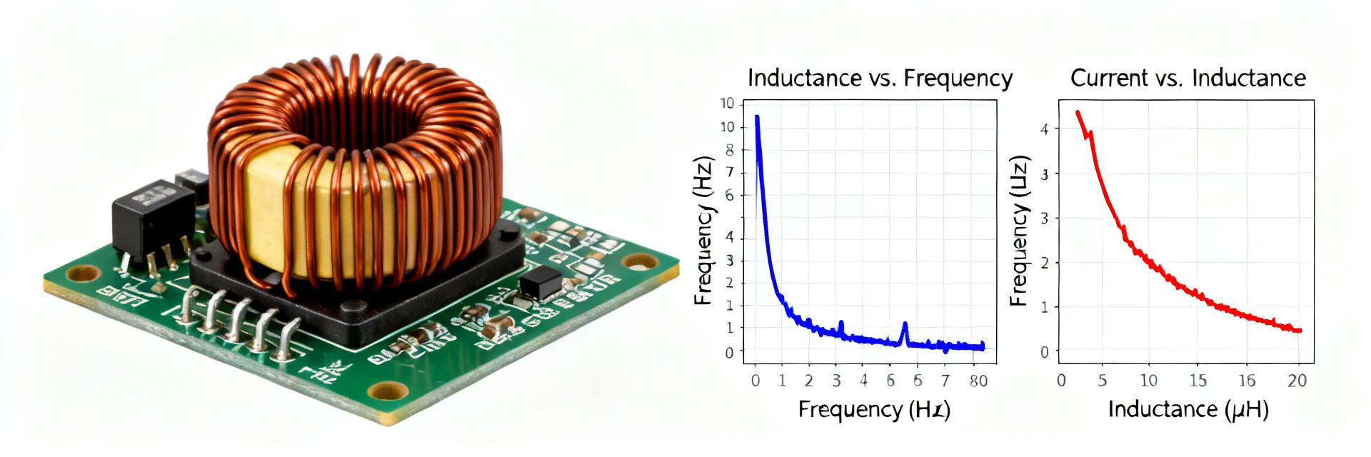
Point: The self-resonant frequency (SRF) and impedance-vs-frequency profile govern the high-frequency limits of this inductor.
Evidence: Impedance plots indicate that above the SRF, the component behaves capacitively, rendering it ineffective as an inductive choke.
Explanation: For switching regulators operating in the 100 kHz to 2 MHz range, ensure the switching frequency and its dominant harmonics remain well below the 18 MHz SRF limit. This safeguards stable converter control and minimizes high-frequency parasitic noise transmission.
(3) Mechanical, mounting & thermal data — Data-driven specs
Package, dimensions & footprint
Point: Strict physical dimension compliance prevents assembly interference and optical inspection failures.
Evidence: Standard 0703 mechanical packaging features a 7.4 mm × 7.0 mm footprint with a 3.0 mm maximum seated height.
Explanation: Confirm your CAD library footprint matches the manufacturer's recommended landing pads (approx. 2.5 mm width per pad with a 3.7 mm internal gap). This ensures proper solder fillet formation during SMD reflow and avoids solder bridging issues in tight layouts.
Thermal limits and derating guidance
Point: Thermal performance directly impacts safe maximum continuous operating currents.
Evidence: The component is rated for a continuous operating temperature range of -55°C to +155°C (ambient temperature plus self-heating temperature rise).
Explanation: If your system ambient temperature exceeds 105°C, you must derate the allowable Irms limit. Ensure there is adequate thermal relief on the connecting copper traces to prevent hot spots from exceeding the +155°C material threshold under full load.
(4) Performance testing, reliability & handling notes
Typical test conditions & representative results
Point: Inductor measurements must be correlated against standard conditions to ensure accurate hardware validation.
Evidence: Inductance-vs-current curves demonstrate a gradual saturation slope, typical of composite iron powder cores.
Explanation: Unlike ferrite cores that exhibit a sharp drop-off in inductance at saturation, the HCM1A0703V3-8R2-R offers soft saturation behavior. This prevents sudden current spikes when transient loads briefly exceed the 6.5 A saturation limit.
Reliability, qualification & storage/handling
Point: Component storage and mechanical handling govern long-term reliability and yield during assembly.
Evidence: The HCM1A0703V3 series is classified under Moisture Sensitivity Level (MSL) 1, meaning it has an unlimited floor life when stored below 30°C and 85% relative humidity.
Explanation: The component is qualified to withstand lead-free reflow peak temperatures up to 260°C (as per J-STD-020 standards). Avoid subjecting the molded body to localized mechanical shock, which can cause micro-cracks in the iron powder matrix.
(5) Quick selection checklist & comparative notes
When to choose HCM1A0703V3-8R2-R (tradeoffs)
Point: Component selection requires balancing size constraints against power conversion efficiency.
Evidence: High-inductance 0703-sized options offer low output ripple but present higher DCR compared to larger 1004 or 1205 form factors.
Explanation: Use this quick selection checklist to verify if the inductor suits your layout:
- Inductance: 8.2 µH meets your converter's ripple current target (typically 20% to 40% of max load).
- DCR Margin: The 43.6 mΩ maximum DCR is acceptable for your target efficiency budget.
- Peak Current: System peak current remains comfortably below the 6.5 A saturation limit.
- Height Constraint: Vertical clearances are greater than the 3.0 mm maximum component height.
One-page quick reference & PCB tips
Point: Implement standard high-frequency layout practices to preserve signal integrity and minimize EMI.
Evidence: Parasitic magnetic fields can couple high-frequency noise into adjacent sensitive analog feedback traces.
Explanation: For optimal results, consult "HCM1A0703V3-8R2-R footprint specs" when configuring your EDA design rules. Always route the feedback trace away from the switching node, and avoid placing any copper planes directly beneath the inductor body on the top layer to prevent eddy current losses.
| Inductance (Nominal) | 8.2 µH |
| Maximum DC Resistance (DCR) | 43.6 mΩ |
| Rated Current (Irms) | 4.8 A |
| Saturation Current (Isat) | 6.5 A |
| Package Footprint (L × W × H) | 7.4 mm × 7.0 mm × 3.0 mm (max) |
Summary
- The HCM1A0703V3-8R2-R delivers a robust, space-efficient magnetic solution featuring an 8.2 µH nominal inductance, low 38.0 mΩ typical DCR, and a shielded footprint designed for high-density automotive power systems.
- Three critical parameters to verify for layout approval: confirm the 4.8 A Irms limit accommodates continuous loads, ensure the 6.5 A Isat handles transient spikes, and verify the switching frequency operates below the 18 MHz self-resonant frequency.
- To maximize thermal margin, place the inductor immediately adjacent to the switching node and use wide copper planes to distribute heat.
Always consult the complete official Eaton HCM1A0703V3-8R2-R datasheet for final engineering verification, complete thermal curves, and tape-and-reel specifications before locking your production BOM.
Frequently Asked Questions
What does the HCM1A0703V3-8R2-R part number decode to?
The part number decodes left-to-right: "HCM1A" designates Eaton's Automotive High Current Power Inductor family; "0703" represents the package dimensions (approx. 7.4 mm x 7.0 mm x 3.0 mm); "V3" points to the latest product revision level; "8R2" signifies a nominal inductance of 8.2 µH; and the "-R" suffix denotes RoHS compliance.
What are the key electrical limitations of this 8.2 µH inductor?
The primary electrical limits include a maximum Direct Current Resistance (DCR) of 43.6 mΩ (38.0 mΩ typical) at 25°C, a Rated Current (Irms) of 4.8 A based on a 40°C temperature rise, and a Saturation Current (Isat) of 6.5 A based on a 30% roll-off in inductance. Operation near or beyond these limits requires careful thermal monitoring.
How should the PCB footprint and layout be optimized for thermal performance?
To maximize thermal performance, place the inductor as close as possible to the switching node. Use wide copper pours connected to the mounting pads, and integrate thermal vias to transfer heat to internal ground/power planes. Avoid routing sensitive analog signal lines directly underneath the inductor's magnetic core.
Is the HCM1A0703V3-8R2-R AEC-Q200 qualified for automotive applications?
Yes, the HCM1A0703V3 series is AEC-Q200 Grade 1 qualified, which certifies it for high-reliability automotive and harsh industrial environments. It supports a wide operating temperature range from -55°C up to +155°C (including self-heating).