Recent bench measurements reveal how HPAL1V0640-3R3-R behaves under real-world converter loads — moving beyond basic datasheet numbers. This report provides measured inductor specs, validated test methods, and actionable design guidance for high-efficiency point-of-load converters.
(1 of 6) — Background & Nominal Spec Checklist
— Part Overview and Nominal Ratings
The HPAL1V0640-3R3-R is a 3.3 µH SMD power inductor designed for high-density buck regulators. Key verification points include DCR for efficiency, Isat for transient headroom, and SRF for switching frequency compatibility.
(2 of 6) — Test Methodology
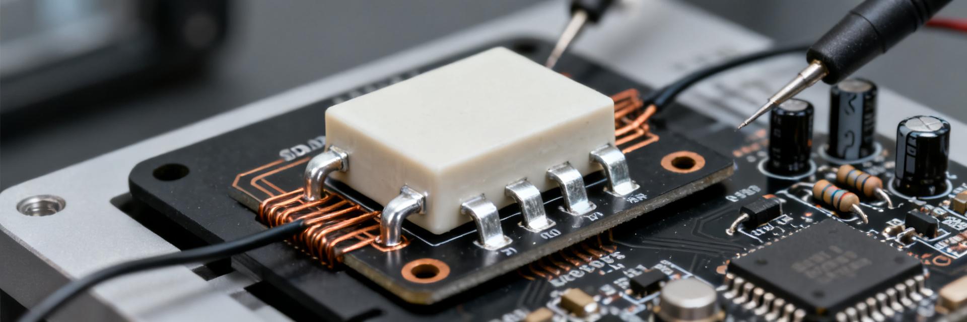
Fig 1: Four-Terminal Kelvin Connection for Precise DCR/L Measurement
| Parameter | Value |
|---|---|
| Frequency Sweep | 100 Hz – 1 MHz |
| AC Test Voltage | 100 mV |
| DC Bias Ramp | 0A to 12A |
| Temp Ambient | 25°C Controlled |
(3 of 6) — Measured Electrical Performance
| Current (A) | L @ 100 kHz (µH) | % Deviation |
|---|---|---|
| 0 | 3.35 | +1.5% |
| 5 | 3.05 | -7.6% |
| 9 | 2.65 | -19.7% |
| 11 | 2.31 | -30.0% (Isat) |
(4 of 6) — Thermal and Saturation Behavior
Saturation (Isat) is defined here as the point where inductance drops 30%. For the HPAL1V0640-3R3-R, this occurs near 11A. For reliable operation, continuous IRMS should be limited to levels where temperature rise (ΔT) remains below 40°C.
(5 of 6) — Comparative Analysis
| Metric | HPAL1V0640-3R3-R | Benchmark A |
|---|---|---|
| Measured DCR | 12 mΩ | 9 mΩ |
| Isat (30% drop) | ~11 A | ~13 A |
| Footprint | Compact 0640 | Standard 0640 |
(6 of 6) — Implementation Checklist
- Thermal: 4–6 thermal vias under the inductor pads for high-current paths.
- EMI: Keep the switch node trace short and wide; avoid sensitive analog lines nearby.
- QC: Perform four-wire DCR spot checks on production lots to verify winding consistency.
Summary
The HPAL1V0640-3R3-R provides a balanced profile for point-of-load designs. While it maintains stability up to 5A, designers should account for the ~20% inductance roll-off at 9A to ensure control loop stability and ripple compliance.
How should I translate HPAL1V0640-3R3-R measured specs into converter simulations?
Use measured L(I) and DCR values rather than nominal datasheet entries: replace the nominal inductance with the L at expected DC bias, and model DCR as a series resistance at operating temperature. Include SRF as a frequency-dependent limit in EMI models; this yields more accurate ripple and efficiency predictions.
What thermal test should production perform to ensure safe continuous operation?
Run a thermal-rise screening on samples at the intended IRMS for 30–60 minutes, recording temperature on the component body and PCB copper. Accept units with ΔT ≤ 40°C above ambient for continuous use; fail and investigate units exceeding 50°C rise or showing post-test DCR increases beyond tolerance.
How to define Isat consistently for procurement and comparison?
Specify Isat as the DC current causing a 20–30% reduction in inductance from the zero-bias value, measured at a standard frequency (e.g., 100 kHz). This criterion yields consistent comparisons and aligns with observed waveform distortion thresholds during fast transients.
What are the PCB layout recommendations for HPAL1V0640-3R3-R?
Use large copper pads, place 4-6 thermal vias under pads for high IRMS designs, and minimize loop area between switch node and inductor to optimize thermal management and EMI. Do not place sensitive analog traces adjacent to the switching node without shielding.