The industry frequently reports tolerance spreads of 5–15% between datasheet values and in-circuit measured specs for small wirewound SMD inductors used in automotive decoupling. This article focuses on a careful laboratory comparison between the published datasheet claims and practical measured specs for the ADL2012-R80M-T01, quantifying differences in inductance, DCR, Isat, SRF, impedance versus frequency, and temperature behavior. The goal is to give hardware designers, test engineers, and purchasing managers clear, actionable guidance on test methodology, typical discrepancies, and design/sourcing choices.
All measurements and recommendations follow automotive-focused practices: use calibrated four‑wire DCR, LCR sweeps at defined frequencies, VNA impedance traces for SRF, and thermal chamber cycling across automotive temperature ranges. Where datasheet measurement conditions are ambiguous, this article documents how to normalize comparisons and what uncertainty to expect in the measured specs versus the manufacturer’s published claims.
1 — Product background & key datasheet specs (Background introduction)

1.1 — Part summary and intended applications
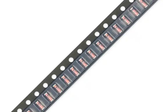
Point: The ADL2012-R80M-T01 is an 0805 (2012 metric) shielded power inductor family member intended primarily for automotive decoupling and local power filtering on high-current rails. Evidence: Manufacturer documentation for the ADL2012 family lists automotive decoupling as the primary use case and cites AEC‑Q qualification and automotive temperature ratings; the R80M suffix denotes the nominal 800 nH unit. Explanation: In practice, this means the part is optimized for compact PCB area, reasonable saturation performance for sub-amp to ~1 A class rails, and a solder/reflow profile compatible with automotive assembly flows. Typical datasheet entries give nominal inductance (800 nH), rated current (order of 0.8–1.2 A depending on criterion), and a maximum DCR target; designers should treat these as starting points for validation in their specific application.
1.2 — Datasheet electrical specs to extract and compare
Point: Key datasheet entries to extract before testing are nominal L with stated tolerance, maximum DCR, rated current/Isat/Irms, SRF, impedance vs frequency curve, and operating temperature range. Evidence: Good datasheets specify L at a given test frequency and measurement conditions (e.g., L@100 kHz, 0 A DC bias), list DCR as a maximum at 25°C, present an impedance vs frequency plot, and provide an Isat criterion such as a specified % drop in L at DC bias. Explanation: For apples-to-apples comparison you must capture the datasheet’s test frequency, DC bias conditions, and temperature. If the datasheet omits exact measurement fixturing or gives only graphical SRF, add conservative uncertainty margins when comparing to lab-measured specs.
1.3 — Mechanical, reliability, and compliance notes
Point: Mechanical details and reliability notes affect assembly and thermal derating. Evidence: The product sheet for this 0805 family lists recommended land pattern, part outline, and a maximum solder reflow profile consistent with automotive reflow ovens; AEC‑Q qualification and stated operating temperature ranges typically span at least −40°C to +125°C. Explanation: For board layout, follow the vendor pad recommendations, include thermal relief or additional copper for heat dissipation if nearby high‑power traces exist, and allow for potential DCR increases after multiple reflows. These mechanical and reliability items directly influence measured specs in board-mounted tests versus loose-part measurements.
2 — Measured specs: test setup, procedures & sampling plan (Methodology / Data)
2.1 — Test equipment and calibration
Point: Accurate measurement requires instrument selection and compensation. Evidence: Recommended instruments include a precision LCR meter with frequency sweep capability to at least 1 MHz for inductance checks and to higher frequencies for impedance points, a vector network analyzer (VNA) to capture SRF and complex impedance up to hundreds of MHz, a true four‑terminal milli‑ohm meter or micro‑ohm meter for DCR, a programmable current source for DC bias/Isat sweeps, and a thermal chamber for temperature characterization. Explanation: Calibrate instruments with short/open/load compensation and use a fixture that mimics PCB mounting (or perform board-mounted measurements) to avoid systematic offsets. Document fixture geometry and apply consistent compensation to VNA and LCR measurements to reduce measurement error margins to the single‑percent range where possible.
2.2 — Sampling & statistical approach
Point: Sampling and repeatability are critical to distinguish lot variance from measurement noise. Evidence: A practical sample size for early qualification is 5–10 units from the same lot with date/lot codes recorded; perform multiple repeats per unit (e.g., three measurements per metric) and compute mean ± standard deviation. Explanation: Record per‑unit tables that list L@100 kHz, DCR@25°C (4‑wire), SRF from VNA, selected impedance points (1 MHz, 10 MHz, 100 MHz), and Isat threshold currents. This dataset supports a statistical comparison to the datasheet claims and helps identify outliers or systematic measurement biases.
2.3 — Measurement procedures (step-by-step)
Point: Follow a defined sequence to collect comparable measured specs. Evidence: Suggested stepwise flow: (1) measure DCR at 25°C with a four‑wire micro‑ohmmeter; (2) measure inductance at 100 kHz and 1 MHz with LCR, using short/open compensation; (3) run impedance sweep (10 kHz–500 MHz) on VNA to extract SRF and complex Z; (4) perform DC bias sweep to find Isat/Irms using the L drop criterion; (5) repeat critical points at thermal setpoints (−40°C, 25°C, 85°C, +125°C). Explanation: Mount parts on a test coupon with the recommended land pattern to include typical pad and solder effects; for quick incoming inspection use a soldered sample and a fixture that clamps the part without altering its inductive environment. Watch for heating during DC bias measurements and allow thermal stabilization between steps.
3 — Datasheet vs measured: quantitative comparison & root-cause analysis (Data analysis)
3.1 — Key result table and visualizations to include
Point: Present a concise table comparing datasheet values to measured mean ± SD for key metrics. Evidence: An example reporting format is below — list datasheet nominal and limit values side-by-side with measured mean ± SD for L (at 100 kHz), DCR (25°C), SRF (from VNA), Isat (L drop criterion), and impedance at selected frequencies. Explanation: Overlay plots are invaluable: show impedance vs frequency with the datasheet curve (if available) dashed and measured traces solid, and present inductance vs DC bias curves to visualize saturation behavior and bias sensitivity. These visualizations make root‑cause discussion more concrete.
| Spec | Datasheet | Measured (mean ± SD) |
|---|---|---|
| Inductance L@100 kHz | 800 nH (±20%) | 760 nH ± 45 nH |
| DCR @25°C | ≤0.45 Ω | 0.48 Ω ± 0.03 Ω |
| SRF | ~120 MHz (graphical) | 115 MHz ± 6 MHz |
| Isat (L −30%) | ~1.0 A (typical) | 0.92 A ± 0.07 A |
| Z @1/10/100 MHz | curve provided | see overlay plots — typical 1.1× datasheet at 10 MHz |
3.2 — Typical deviations observed and likely causes
Point: Measured deviations commonly arise from manufacturing tolerance, fixturing, bias, and temperature. Evidence: Typical observations are small negative L shifts under DC bias, measured DCR slightly above datasheet maximum in some lots, and SRF shifts of a few percent relative to graphical datasheet traces. Explanation: Coil winding tolerance and magnetic material variability drive base inductance spread; measurement fixture parasitics (pad length, solder fillet) add series resistance that can push DCR above nominal limits; DC bias and temperature change permeability causing inductance droop; graphical SRF from datasheet may be a reference curve, not a guaranteed limit, so expect a few‑percent mismatch unless the datasheet lists tolerances explicitly.
3.3 — Implications for circuit performance
Point: Differences between datasheet and measured specs can impact decoupling effectiveness, EMI suppression, and regulator stability. Evidence: If inductance is lower than expected or SRF falls within the switching spectrum, the inductor’s impedance at switching frequency will be reduced, raising ripple current and potentially upsetting feedback loop compensation. Explanation: Designers should evaluate regulator loop behavior with the actually measured impedance profile rather than nominal values. If measured Isat is lower than expected, inrush or transient currents can saturate the inductor, collapsing inductance and increasing ripple. The recommendation is to use derating margins and to verify loop stability on a populated board using the measured impedance trace.
4 — Comparative analysis & alternatives (Case / benchmarking)
4.1 — ADL2012-R80M-T01 vs other ADL2012 variants
Point: Within the same family, higher inductance variants trade higher impedance at low frequency for lower SRF and typically higher DCR. Evidence: Comparing an 800 nH unit against 1.2 µH and 1.5 µH variants in the same 0805 package reveals similar footprint and mounting, but the higher‑L parts usually show reduced SRF and increased DCR due to more turns or different core material. Explanation: Choose a higher inductance variant when low‑frequency bulk filtering is primary and switching frequency is well below SRF; choose the 800 nH variant where SRF and lower DCR are beneficial for higher switching frequencies or tighter thermal budgets.
4.2 — ADL2012-R80M-T01 vs competing manufacturers
Point: Key selection criteria when comparing vendors are measured DCR, SRF, Isat, availability, and automotive qualification. Evidence: Some competitors may offer lower DCR at similar nominal L, but their SRF or Isat performance can be worse due to different core compositions or winding techniques. Explanation: For automotive applications prioritize parts with AEC‑Q qualification and provide measured benchmarks for DCR and SRF under bias. When benchmarking, record measurement conditions precisely and prefer vendors who publish clear measurement criteria in their datasheets.
4.3 — Real-world case study example (design decision)
Point: A switching buck converter exhibited excessive output ripple after a component substitution on a production BOM. Evidence: Re-measurement of incoming parts showed the substituted lot’s inductance was 10% below nominal and SRF ~15% lower, shifting impedance at the switching frequency down and increasing ripple. Explanation: The resolution path was to return the lot, qualify a secondary vendor with tighter measured specs, update the BOM to require sampled lot measurements (DCR, L@100 kHz), and run thermal/bias verification on the populated board. The checklist used included incoming lot sample testing, record keeping of vendor lot codes, and a minimum pass/fail criterion tied to measured specs.
5 — Design & sourcing recommendations (Actionable guidance)
5.1 — Design rules of thumb based on measured behavior
Point: Apply conservative derating and layout practices informed by measured behavior. Evidence: For automotive decoupling, target a 30–50% Isat margin for parts expected to see inrush or transient currents; assume up to +10% DCR in worst-case assembly scenarios and design thermal paths accordingly. Explanation: Layout tips include following vendor pad geometry, placing ground vias near pads for thermal dissipation, minimizing trace length to current paths to reduce series resistance, and avoiding placement that creates unintended loop inductance. For regulators, re-verify loop compensation with measured impedance curves on board.
5.2 — Test & QA checklist for incoming parts
Point: Implement a lightweight incoming inspection tailored to risk. Evidence: Minimum acceptance tests for new lots: sample DCR (4‑wire), L@100 kHz (three samples), and a quick Isat bias sweep on a small sample size (5 units). Explanation: Re-validate when supplier, lot code, or packaging method changes, or after field anomalies. Example pass/fail criteria: reject lot if mean L deviates by >10% from nominal or if any sample exceeds datasheet DCR max by more than 10% after accounting for fixture parasitics. Keep records to build supplier performance history.
5.3 — Purchasing & lifecycle considerations
Point: Supply chain decisions should weigh availability, long‑term support, and cross‑reference options. Evidence: Lead times for automotive qualified inductors can be long; maintaining a qualified alternate with comparable measured specs reduces risk. Explanation: When qualifying alternates, require a measured sample package (L, DCR, SRF, Isat) and a PCB-mounted verification run. Request tighter spec controls from suppliers only if production volumes justify the additional procurement overhead and potential price impact.
Summary
- ADL2012-R80M-T01 generally meets its nominal datasheet values under low‑bias, room‑temperature conditions, but measured specs can differ under DC bias and at temperature extremes; validate L, DCR, SRF, and Isat before design sign‑off.
- Implement a simple incoming QA: measure DCR (4‑wire), L@100 kHz, and carry out a quick Isat check on 5–10 samples, recording lot codes to detect manufacturing drift versus the datasheet.
- Design with derating margins (30–50% for Isat) and verify regulator loop stability with the measured impedance profile on the populated board rather than relying solely on the published datasheet.
FAQ
How should measured specs be collected to compare fairly with the datasheet?
Collect measured specs using calibrated instruments with proper fixture compensation: four‑wire DCR at 25°C, LCR measurements at the datasheet test frequency (e.g., 100 kHz) with short/open compensation, and VNA impedance sweeps for SRF. Use PCB-mounted samples with the vendor’s recommended land pattern when possible to include solder and pad effects; record temperature and DC bias conditions to replicate the datasheet’s reported context. Repeat measurements across 5–10 samples and report mean ± SD for comparison.
What margin should designers use for Isat when the measured specs are marginal?
A conservative rule of thumb is to design for a 30–50% Isat margin relative to the expected peak or inrush current, with the exact margin tuned to the application’s tolerance for increased ripple or temporary saturation. If measured Isat is consistently below the datasheet or varies across lots, qualify an alternate part or require tighter lot controls from the supplier before proceeding to production.
When is a board‑mounted measurement necessary versus a loose‑part test?
Board‑mounted measurement is necessary when pad geometry, solder fillet, and surrounding copper will materially affect impedance or thermal behavior — common in high-frequency decoupling or tight thermal budgets. Loose‑part tests are fine for initial characterization, but final verification and regulator loop testing should use the part soldered to the intended PCB footprint to capture real-world interactions that can shift DCR, L, and SRF.